


In spring last year we took on a project for an automotive tier-2 supplier in Querétaro, Mexico. They had just installed six new 6-axis welding robots on a shared production line for truck chassis components. The machines themselves were certified, but the perimeter around them was not — the integrator had left only a temporary chain-link fence, and the plant’s safety audit would not sign off until a fixed machine guarding system was in place. The line had to be running within three weeks.
The customer first asked for a standard welded mesh fence similar to what they used in the warehouse. Our safety engineer pushed back after reviewing the robot reach diagrams. A welding cell is not a warehouse aisle: it has moving arms that can throw sparks, pinch points that move at 2 m/s, and operators who need to load parts without opening the whole cage. We proposed a dedicated machine guarding system instead. This case walks through what we designed, what we shipped, and how the install went.

Why the Temporary Chain-Link Fence Had to Go
The existing chain-link barrier was put up by the robot integrator just to keep people out during commissioning. It was never going to pass a real safety audit, and the plant EHS officer had flagged it within a week.
Reach distance and opening size
ANSI/RIA R15.06 and ISO 10218 both require that the opening in a perimeter guard is small enough that a person cannot reach a moving part through the mesh. Chain-link at 50 mm openings fails that rule once the robot arm is inside. We switched to 20 × 100 mm mesh, which stops fingers and hands from reaching through, and set the fence at 1.5 m from the maximum robot reach envelope — the minimum safe distance the audit required.
Spatter and arc flash protection
Welding cells throw spatter and UV arc light. Plain mesh lets both through to the walkway. We added 1.2 m high transparent polycarbonate vision windows on the operator side, so supervisors could watch the weld without opening the gate, and spark-resistant mesh panels on the back side facing the robot torch.
Interlocked access, not just locks
A standard padlock gate is not enough for a robot cell. Every gate into the perimeter needs a safety interlock switch that cuts robot power the moment the door opens, and a time-delay release so the arm has time to stop. We specified magnetic safety interlocks with 30-second off-delay, wired into the cell’s safety PLC.
Final Specs We Supplied
After two drawing reviews with the integrator’s controls engineer, we locked the following BOM. These are the actual dimensions shipped.
Perimeter panels and posts
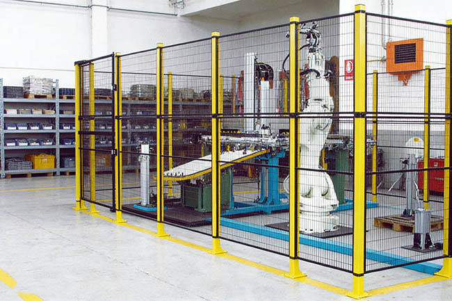
The cage was 18 m long × 9 m wide × 4.2 m high, enclosing six robots and two part-loading stations. Panels were 4.2 m high × 1.5 m wide, welded mesh 20 × 100 mm, 4 mm wire, framed in 40 × 40 × 2 mm tube. Posts were 80 × 80 × 2.5 mm square tube, floor-anchored with four expanding bolts each, powder-coated safety yellow RAL 1023. Total perimeter was around 54 meters.
Vision windows and spark panels
On the operator-facing long side, every third panel was replaced with a 4.2 m high × 1.5 m wide clear polycarbonate window, 5 mm thick, UV-stabilized. On the robot torch side, we supplied steel sheet infill from 0.5 m to 1.8 m high to take spatter, with mesh above for ventilation. The roof was left open — the plant’s exhaust system pulled welding fumes out through the ceiling.
Safety gates and interlocks
We supplied three 1000 mm single-leaf personnel gates for routine access, each with a magnetic safety interlock, internal push bar and external key switch. At each end of the line we installed a 2500 mm double-leaf sliding gate for forklift access during fixture changeover, with a separate interlock and a hold-to-run button outside the cage. All gate frames were welded steel, powder-coated to match the yellow posts.
Installation and Commissioning
The customer had a 72-hour window over a long weekend to install and commission the cage, because the line could not stop during normal production. We packed the order by station — each robot cell got its own numbered pallet — and our lead installer flew down to Querétaro for the first two days.
Floor layout and anchoring
The floor was existing concrete, already painted. Our crew used the paper layout template we sent, marked post positions, drilled 14 mm holes and fixed the 200 × 200 mm floor plates with chemical anchors. No core drilling through the slab, no concrete patching. The whole perimeter layout took about four hours on day one.
Panel assembly and interlock wiring
Panels clipped to the posts with bolt-on brackets — no welding on site, which kept the install clean and fast. The local electrician, supervised by our controls engineer, wired the three personnel interlocks and the two sliding-gate interlocks into the cell safety PLC. We ran a full stop-time test on each gate: open the door, confirm the robot cuts power within the specified stop category, confirm the 30-second delay before reset. All five gates passed on the first try.
Handover and Audit Result
The plant EHS officer and the integrator’s safety engineer walked the cage on Monday morning. They checked reach distances, mesh openings, interlock stop times, emergency stop buttons inside the cage, and the fire egress path through the push-bar gates. The audit passed with no observations. The line started production on schedule that afternoon.
Six months later, the customer told us they have expanded the same guarding system to two more welding cells, using the same panel size, yellow finish and interlock spec. Standardizing across cells means their maintenance team keeps one set of spare parts on the shelf and their electricians already know how the interlocks wire up.
If you are integrating a new robot cell, stamping press, packaging line or any automated machine that needs a fixed perimeter guard, contact BDINDUSTRIAL. Send us the machine reach diagram, your required safety standard (ANSI R15.06, ISO 10218, or local code) and your target install window. We will come back with a panel layout, gate positions and an itemized quote within one working day.
FAQ
1. How high should a machine guarding fence be?
For robotic cells and moving machinery, 2000 mm is the minimum accepted height in most codes. High-energy applications — press brakes, stamping lines, large robots — usually go to 2400 mm or 4200 mm to match the machine reach. The exact height is set by the safety distance calculation in your risk assessment, not by a default number.
2. Can the safety interlocks be wired to our existing PLC?
Yes. We supply the interlock switches with standard safety contacts (NC/NO pairs) that integrate directly into most safety PLCs and safety relays. Tell us your PLC brand and safety category requirement (Cat 3 / PLd / SIL 2) and we will recommend the right switch model.
3. Do you supply the polycarbonate vision windows and spark-resistant panels?
Yes. Clear polycarbonate windows, steel sheet infill for spatter zones, and ventilation mesh are all available as panel options. We can mix panel types on the same perimeter — clear on the operator side, solid on the torch side — without changing the post system.
4. What is the typical lead time for a robot cell guarding project?
Standard panels in safety yellow ship in 15–20 working days after drawing confirmation. Custom heights, special interlock brands or large perimeter runs add 5–10 days. On-site installation for a 50–60 m perimeter usually takes 2–4 days with a crew of 4–6.
5. Can you help with the safety distance calculation and audit documentation?
We provide general arrangement drawings, reach-distance diagrams and a material spec sheet to support your risk assessment. The formal risk assessment and certification are usually signed off by your integrator or a local safety engineer, but our drawings are formatted to drop straight into that documentation.